- 01: Introduction
- 02: History
- 03: Propellants, Firearms, and Ammunition Development
- 04: Modern Firearms Manufacture
- 05: Small Arms Ammunition
- 06: Evidence Handling Procedures
- 07: Equipment and Instrumentation
- 08: Examination of Firearms
- 09: Cartridge and Shotshell Examination
- 10: Characterization and Evaluation of Fired Projectiles
- 11: Bullet Comparison and Identification
- 12: Gunshot Residue and Distance Determination
- 13: Toolmark Identification
- 14: Communicating Results
- Resources


Reverse Lighting Technique
Home > Toolmark Identification > Toolmark Examination > Reverse Lighting Technique

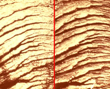
Comparison of a fracture in plastic using
the reverse lighting technique
To document fractured comparisons, the objects should be viewed side-by-side on separate stages of a comparison microscope. The fractured surface of each specimen can be made to appear as a mirror image of the other on each side of the optical hairline through the use of the reverse lighting technique. The results are very graphic and convincing in demonstrating that the two objects were once joined together, especially after image documentation is generated.
The following steps are a guide for conducting an examination using reverse lighting:
- Orient both items such that they appear to be in their original position relative to each other.
- Place the items on a laboratory bench running from left to right.
- Make an index mark (using a permanent marker) from one corresponding surface to the other, crossing over the interface where the fracture apparently occurred. For instance, if a fractured rod appears to have once been joined, place an indexing mark on the two sections so that the index mark crosses over the fracture line from left to right.
- Hold the temporarily “joined” specimens so that the indexing line produced by the permanent marker is vertical and facing toward the examiner.
- Rotate the top end of the upper specimen 180 degrees and embed the nonevidentiary end in a specimen holder (clay, plasticine, etc.) on the left stage of the microscope with the indexing mark facing toward the examiner.
- Embed the bottom end of the lower specimen in a specimen holder on the right stage of the microscope with the indexing mark facing toward the examiner.
The end result of the placement of the specimens on their respective stages will be two questioned fractured objects prepared for comparison using reverse lighting. - Arrange the microscope lights for grazing illumination, one arranged in the conventional way (directed toward the examiner from the back of the microscope) and one in an unconventional way (mounted in the front of the stage directed away from the examiner).
- Bring both items into focus at low illumination for a side-by-side comparison.
- Note that although the two surfaces are different (high points on one are low points on the other), the shadows generated give the appearance of two mirror images on either side of the optical hairline because one of the lights is reversed by 180 degrees.
- The area of best agreement should be documented, preferably by digital or conventional photography or by other means, as determined by laboratory protocol. Images should be marked with the examiner’s initials, case identifier, degree of magnification, item numbers, and a description of the nature of the observed area.
- Examine both items for the presence of manufacturing marks. Manufacturing marks provide corroborative information that can further support the fracture identification. These marks should also be documented by some type of imaging.
- Examine the alignment of the broken edges of both items at ninety degrees to the fractured surface for additional corroboration. Imaging should be used to support the overall conclusion.
Fracture matches (physical matches) typically represent a small percentage of the toolmark caseload, but may be encountered in some cases, such as in terrorism incidents involving fractured bomb components.

Click here to read a sample forensic worksheet and report -
Toolmark Identification (Fractures)


